
16550 UART Hardware Flow Control: What Every BIOS Engineer Should Know

By David Zhu | GDBplus
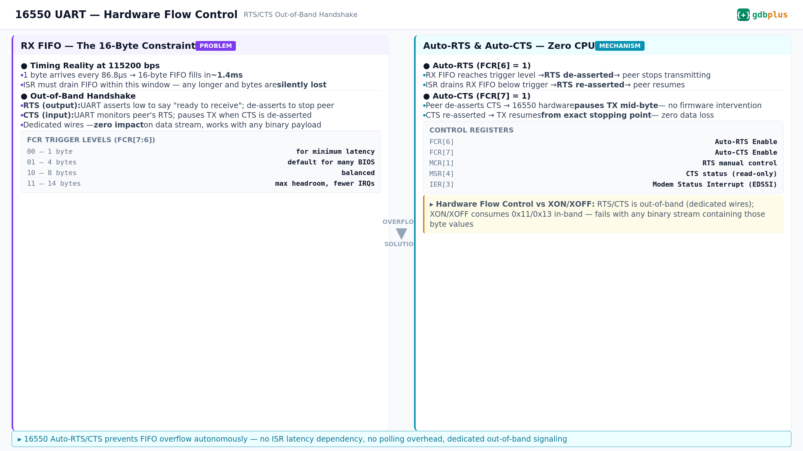
If you’ve ever debugged a firmware hang by watching serial output, you’ve trusted the 16550 UART to deliver every byte. But here’s the uncomfortable truth: at 115200 bps, that 16-byte RX FIFO fills in 1.4 milliseconds. If your ISR doesn’t drain it in time — and in a BIOS environment, SMI handlers, PCI enumeration storms, and DXE dispatcher overhead all compete for CPU — the bytes are silently gone.
RTS/CTS hardware flow control is the fix. Let’s walk through what the 16550 actually does when FCR[6] and FCR[7] are set
.
1. The Problem: Why BIOS Serial is Fragile
The 16550 is the workhorse UART in PC platforms. The Super I/O (or eSPI-attached EC) exposes it. EDK2’s SerialPortLib talks to it. And it has a 16-byte FIFO.
At 115200 bps, with 8N1 framing:
▸ 1 byte on the wire: (1 start + 8 data + 1 stop) / 115200 = 86.8 μs
▸ 16-byte FIFO fills in: 16 × 86.8 μs = 1.39 ms
▸ Your ISR deadline: drain the FIFO in under 1.39 ms, every time, forever
In a real BIOS boot path, 1.39 ms is nothing. An SMI can hold the CPU for hundreds of microseconds. PEI memory initialization can block for milliseconds. A single PCI config space read that triggers an SERR# can stall long enough to overflow the FIFO.
The result? Silent data loss. The UART’s Line Status Register won’t flag an overrun until it’s already happening — and by then you’ve lost bytes you can’t recover. Your debug log has gaps. Your console redirection drops characters. And you spend hours chasing a bug that doesn’t exist in the code.
2. Out-of-Band Signaling: RTS and CTS
Hardware flow control uses two dedicated signal lines that operate independently of the TXD/RXD data path:
▸ RTS (Request to Send) — UART output. When the 16550 asserts RTS (drives it low), it’s telling the remote peer: “I’m ready, send data.” When RTS goes high, it means: “Stop now.”
▸ CTS (Clear to Send) — UART input. The 16550 monitors this pin. When the remote peer de-asserts CTS, the 16550 stops transmitting — no firmware action needed.
This is out-of-band signaling. The RTS/CTS state changes consume zero bits of the data stream. Unlike XON/XOFF (which embeds 0x11/0x13 in the data), RTS/CTS works identically whether you’re sending ASCII debug text or raw binary firmware capsule updates.
3. The Registers That Matter
In a BIOS codebase (EDK2 or coreboot), you touch these registers:
▸ FCR (FIFO Control Register, offset 2, DLAB=0 required)
Bit 0: FIFO Enable (must be 1 for auto flow control)
Bit 6: Auto-RTS Enable — hardware manages RTS autonomously
Bit 7: Auto-CTS Enable — hardware responds to CTS autonomously
Bits 7:6 (Write-only FCR): RX FIFO trigger level (00=1, 01=4, 10=8, 11=14 bytes)
▸ MCR (Modem Control Register, offset 4)
Bit 1: RTS manual control — only relevant when Auto-RTS is off
▸ MSR (Modem Status Register, offset 6)
Bit 4: CTS pin state (read-only)
▸ IER (Interrupt Enable Register, offset 1, DLAB=0)
Bit 3: EDSSI — Modem Status Interrupt, fires on CTS/DSR/DCD/RI changes
Real EDK2-style initialization:
//
// Configure 16550: enable FIFO + Auto-RTS + Auto-CTS
// Trigger level: 14 bytes (FCR[7:6] = 11)
//
UINT8 FcrValue = (UINT8)((0x3 << 6) |   // Trigger at 14 bytes
                          (0x1 << 3)  |   // DMA Mode Select
                          (0x1 << 0));     // FIFO Enable
IoWrite8 (gSerialIoBase + FCR_OFFSET, FcrValue);

//
// Read back IIR (offset 2, same address as FCR but read-only)
// to verify FIFOs are enabled (IIR[7:6] = 11 for 16550)
//
UINT8 IirValue = IoRead8 (gSerialIoBase + IIR_OFFSET);
if ((IirValue & 0xC0) == 0xC0) {
  DEBUG ((EFI_D_INFO, "16550 FIFO + Auto Flow Control active\n"));
}
4. Auto-RTS: The Hardware Automaton
When FCR[6] = 1, the 16550 contains a comparator that tracks the RX FIFO fill level against the trigger threshold. The sequence is:
RX FIFO crosses the trigger level → hardware de-asserts RTS (drives it high) on the next bit boundary
Remote peer detects RTS change → stops transmitting after the current byte completes
Your ISR fires, reads the FIFO, FIFO drops below trigger
Hardware re-asserts RTS (drives it low) → remote peer resumes
This entire loop runs in hardware. The critical path from “FIFO hits trigger” to “RTS changes” is measured in nanoseconds — it’s comparator → output pin, no firmware in the loop.
Trigger level trade-off for BIOS use:
▸ 1 byte (FCR[7:6]=00): ISR fires for every byte. Lowest latency, highest CPU overhead. Almost never used in BIOS.
▸ 4 bytes (FCR[7:6]=01): Conservative. Many BIOS defaults. Leaves 12 bytes of headroom.
▸ 8 bytes (FCR[7:6]=10): Balanced. About 700 μs between interrupts at 115200 bps.
▸ 14 bytes (FCR[7:6]=11): Fewest interrupts. But only 2 bytes of slack (16 - 14 = 2). At 115200, that’s 174 μs for the remote peer to react to RTS — tight but workable for modern UARTs.
BIOS-specific note: During SMM entry, the CPU saves state and the SMI handler runs in SMRAM. If the SMI handler takes 300 μs, a 14-byte trigger level means you have only ~174 μs of slack after RTS de-asserts. If the remote peer’s RTS detection latency exceeds that window, bytes 15 and 16 can still be lost even with Auto-RTS enabled. For SMI-heavy firmware, consider a 8-byte trigger level for more margin.
5. Auto-CTS: Transparent TX Gating
When FCR[7] = 1, the 16550’s TX state machine is gated by the CTS input:
▸ Remote peer de-asserts CTS → 16550 pauses TX mid-byte if necessary
▸ CTS re-asserted → TX resumes from the exact stopping point
▸ The THR (Transmit Holding Register) maintains its contents
The firmware writes to THR as usual. The hardware handles the rest. Your SerialPortWrite() function in SerialPortLib doesn’t need to check CTS — the chip does it.
Common BIOS bug: I’ve seen platforms where Auto-CTS is enabled but the CTS pin is unconnected (floating) on the board. The 16550 sees a random logic level and either blocks TX permanently or lets it through. The symptom: serial output works on some boards and is completely dead on others. The fix: a pulldown resistor on CTS, or disabling Auto-CTS if RTS/CTS handshake isn’t physically wired.
6. Manual Flow Control: When You Can’t Use Auto
If your platform’s 16550 variant doesn’t support Auto-RTS/CTS (some older clones don’t), you can implement flow control in firmware using MCR and MSR:
Polling approach (PEI phase, before interrupts):
while (BytesToSend > 0) {
  // Wait for THR empty
  while ((IoRead8 (Base + LSR_OFFSET) & B_THR_EMPTY) == 0);
  // Check CTS before writing
  if ((IoRead8 (Base + MSR_OFFSET) & B_CTS) != 0) {
    IoWrite8 (Base + THR_OFFSET, *Buffer++);
    BytesToSend--;
  }
  // If CTS is de-asserted, spin — peer isn't ready
}
Interrupt-driven (DXE phase):
// In SerialPortLib initialization:
// Enable Modem Status Interrupt (EDSSI)
IoWrite8 (Base + IER_OFFSET, (B_RX_AVAILABLE | B_THR_EMPTY |
                                B_RX_STATUS   | B_MODEM_STATUS));

// The ISR checks IIR to identify the interrupt source:
UINT8 IirValue = IoRead8 (Base + IIR_OFFSET);
if ((IirValue & IIR_MODEM_STATUS) != 0) {
  // CTS changed — re-evaluate TX readiness
  UINT8 MsrValue = IoRead8 (Base + MSR_OFFSET);
  if ((MsrValue & B_CTS) != 0) {
    // CTS is asserted, resume transmitting
    ResumeTransmit();
  }
}
The problem with manual flow control: latency. From CTS change to ISR execution, you’ve got interrupt controller latency + CPU interrupt gate delay + potential SMI preemption. In BIOS, this can easily exceed 100 μs. At 115200 bps, that’s a full byte missed.
Auto flow control (FCR[6]=1, FCR[7]=1) eliminates this entirely. The hardware reacts in nanoseconds.
7. Hardware Flow Control vs. XON/XOFF
If you’re debugging a BIOS, you’re sending binary data: firmware capsule updates, memory dumps, PCI config space hex dumps, compressed debug payloads. That makes the choice clear.
▸ Signal path: RTS/CTS uses dedicated physical wires, completely outside the data stream. XON/XOFF injects 0x11 (XON) and 0x13 (XOFF) directly into the byte stream.
▸ Binary compatibility: RTS/CTS works with any data — hex dumps, raw flash images, compressed logs. XON/XOFF breaks catastrophically when 0x11 or 0x13 appears in the payload.
▸ Response latency: RTS/CTS is hardware-level (nanoseconds). XON/XOFF requires the receiving UART to recognize the byte, generate an interrupt, and have the ISR process it — easily 50–100 μs in BIOS.
▸ Hardware requirement: RTS/CTS needs five wires (TXD, RXD, RTS, CTS, GND). XON/XOFF needs only three (TXD, RXD, GND).
▸ Real BIOS scenario: You’re capturing a full PCI config space dump over serial at 921600 bps. The hex dump contains bytes 0x00–0xFF uniformly. XON/XOFF will randomly pause and resume your stream based on data content. RTS/CTS won’t.
Bottom line for BIOS engineers: If you’re doing any serial communication that involves binary data — and most BIOS debugging does — hardware flow control is not optional. It’s the only reliable option.
8. Common Pitfalls in BIOS Environments
▸ DLAB gate: FCR lives at I/O offset 2, but only when LCR[7] (DLAB) = 0. If you write FCR while DLAB is set, you’re writing to the divisor latch instead. Your “flow control enable” silently becomes a garbage baud rate divisor.
▸ FIFO must be enabled first: Auto-RTS and Auto-CTS are features of the FIFO mode. If FCR[0] = 0 (16450 compatibility mode, no FIFO), FCR[6] and FCR[7] are ignored. This catches platforms that set FCR in two separate writes — a “FIFO enable” write followed by a “flow control” write — where an intermediate read flushes the write-only FCR state.
▸ SMI latency breaks Auto-RTS: 14-byte trigger at 115200 bps leaves only 174 μs of slack. If SMI handlers consume 200+ μs, the remote peer may not have time to react to RTS de-assertion before bytes overflow. Test with worst-case SMI duration, not average.
▸ Floating CTS pin: Auto-CTS (FCR[7]=1) with unconnected CTS pin → random TX behavior across boots and boards. Always verify CTS is either physically connected or pulled to an active-low (asserted) state with a resistor.
▸ Super I/O configuration dependency: The 16550 inside a Super I/O (like NCT6796D or IT8625E) may default to RTS/CTS pins disabled. You must configure the Super I/O’s Logical Device registers (usually via LPC/eSPI at 0x2E/0x4E) to enable the UART’s RTS/CTS pins before the 16550 registers have any effect.
▸ EDK2 SerialPortLib: Most SerialPortLib implementations don’t configure flow control — they just set baud rate and enable the FIFO. If your platform needs hardware flow control, you’ll need to customize SerialPortInitialize() to write FCR with the Auto-RTS/CTS bits set.
Summary
Two bits. FCR[6] and FCR[7]. That’s all it takes to transform your serial port from a best-effort debug channel into a reliable transport. The hardware automaton inside the 16550 handles the rest — no ISR latency to worry about, no polling loops, no silent data loss.
For BIOS engineers shipping platform firmware, hardware flow control isn’t a nice-to-have. It’s the difference between debug logs you can trust and debug logs that lie to you.
This article is part of the GDBplus firmware internals series. Full annotated source code walkthroughs: gdbplus.substack.com
#UEFI #BIOS #Firmware #16550 #EDK2 #Embedded