
eSPI EC/SIO UART Access and Enablement in UEFI BIOS

Linkedin: Click David Zhu
The serial port has been the firmware engineer’s eyes and ears for decades. But the physical path from CPU to UART has fundamentally changed. LPC gave way to eSPI, and the debug UART that used to live on a simple Super I/O chip now hides behind an Embedded Controller on a 4-wire serial bus. This article traces that path — from the eSPI bus to the UEFI driver stack — and shows exactly how to access and enable EC/SIO UARTs on modern platforms
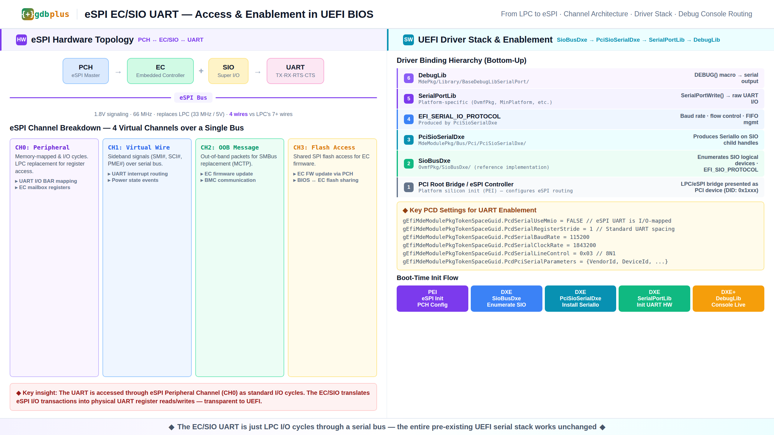
.
Why eSPI Replaced LPC
The Low Pin Count bus served firmware well for 20 years, but it had three fatal flaws for modern platforms.
▸ Pin count: LPC required 7–13 pins. In a world where every pin on a 12×12 mm package is contested real estate, that is a luxury.
▸ Voltage: LPC ran at 3.3V signaling. Modern silicon is 1.8V and below. Level shifters add cost, latency, and board area.
▸ Speed: LPC topped out at 33 MHz. Firmware images grew from 2 MB to 32 MB. Every millisecond of boot time matters.
eSPI solves all three. Four wires (CS#, CLK, MOSI, MISO). 1.8V signaling. 66 MHz with double-data-rate transfers giving effective throughput of 132 Mbps per channel. And critically — it is a packetized serial protocol, not a parallel bus, which means it can carry multiple logical channels over the same physical wires.
The Four eSPI Channels
The eSPI specification (Intel document 327432) defines four virtual channels multiplexed over a single physical bus. Understanding which channel carries what is the key to debugging UART access issues.
▸ Channel 0 — Peripheral Channel: This is the LPC replacement. It carries memory-mapped I/O cycles and I/O-mapped I/O cycles. When UEFI reads or writes a UART register (I/O port 0x3F8 for COM1), the transaction travels over Peripheral Channel as a standard I/O read/write cycle. The EC or SIO decodes it and performs the actual UART hardware access. From the PCH’s perspective, it is talking to an LPC device through a serial tunnel.
▸ Channel 1 — Virtual Wire Channel: Sideband signals that used to have dedicated pins on LPC — SMI#, SCI#, PME#, SERIRQ — are now serialized as virtual wire messages. The UART interrupt line (typically IRQ4 for COM1) rides on Virtual Wire as an SERIRQ message.
▸ Channel 2 — OOB Message Channel: Out-of-band messaging. This replaces SMBus for EC communication. MCTP (Management Component Transport Protocol) packets flow here. Not directly relevant to UART access, but critical for EC firmware updates and BMC interactions.
▸ Channel 3 — Flash Access Channel: Shared SPI flash access. The EC can access the system SPI flash through this channel for firmware updates. BIOS and EC firmware can share a single SPI flash chip.
The critical insight for UART debugging: The UART appears on Channel 0 as standard I/O cycles. The entire pre-existing UEFI serial stack — PciSioSerialDxe, SerialPortLib, DebugLib — works completely unchanged. The EC/SIO translates eSPI I/O transactions into physical UART register reads and writes transparently. If you can talk to the eSPI controller, you can talk to the UART.
Real Hardware: Two Common Configurations
The eSPI ecosystem has converged on two dominant patterns: the EC (Embedded Controller) in mobile platforms, and the SIO (Super I/O) in desktop and server platforms.
Configuration A: EC-Based (Laptop/Notebook)
▸ Chip: Microchip MEC15xx — a dedicated Embedded Controller with eSPI slave interface
▸ Topology: PCH (eSPI Master) → eSPI Bus → MEC15xx (Slave) → Internal UART Block → UART TX/RX pins routed to debug header
▸ UARTs: MEC15xx typically exposes 2–3 16550-compatible UARTs. One is dedicated to debug output, another may be used for serial peripheral communication (touchpad, battery gas gauge).
▸ EC firmware: The MEC15xx runs its own firmware (typically Microchip’s MEC15xx SDK). The EC firmware must configure the UART pin mux and enable the UART clock before UEFI can access it. If UEFI DEBUG() output is silent, the first thing to check is whether EC firmware actually enabled the UART routing.
▸ Register access: From UEFI’s perspective, the UART appears at a standard I/O base address (e.g., 0x3F8). The PCH’s eSPI controller translates I/O cycles in that range into Peripheral Channel transactions targeting the EC. The EC’s hardware auto-decoder routes them to the UART block.
Configuration B: SIO-Based (Desktop/Server)
▸ Chip: ITE IT8628E — a Super I/O controller with eSPI interface
▸ Topology: PCH (eSPI Master) → eSPI Bus → IT8628E (Slave) → Logical Device UART1/UART2 → Physical COM port headers
▸ UARTs: IT8628E typically provides 2–4 fully independent 16550-compatible UARTs, each with its own logical device number (LDN). LDN 0x01 is usually UART1, LDN 0x02 is UART2, and so on.
▸ SIO register model: Unlike the EC model where register access is transparent, the IT8628E uses the classic Super I/O configuration model: enter configuration mode by writing 0x87 to the config port (typically 0x2E or 0x4E), select a logical device, enable it, set the I/O base address, and exit configuration mode. This must be done in PEI or early DXE before PciSioSerialDxe enumerates the device. The EFI_SIO_PROTOCOL’s RegisterAccess() function handles this enter/exit sequence.
▸ eSPI implications: On the IT8628E, configuration register access also goes through eSPI Peripheral Channel. The SIO configuration ports (0x2E/0x2F or 0x4E/0x4F) are routed over eSPI as standard I/O transactions. No special handling is needed — but the eSPI controller must be initialized first.
The UEFI Driver Stack
The EDK2 driver stack for eSPI-based UART access is identical to the legacy LPC stack because eSPI abstracts the transport. Here is the full chain.
Layer 1 — PCI Root Bridge / eSPI Controller
The PCH’s eSPI controller appears as a PCI device (typically Device 1F, Function 0 on Intel platforms, DID 0x1Fxx range). Platform silicon initialization in PEI configures the eSPI frequency, I/O decode ranges, and channel enables. If this layer is misconfigured, all downstream devices are invisible.
Key PEI responsibilities from MdePkg/Include/Ppi/SuperIo.h:
EFI_SIO_REG(ldn, reg)          // Pack logical device + register into a single UINT16
EFI_SIO_LDN_GLOBAL             // Special LDN for global SIO registers (0xFF)
Layer 2 — SioBusDxe
The SioBusDxe driver (OvmfPkg/SioBusDxe/) is the reference implementation for Super I/O bus enumeration. It creates child handles for each logical device on the SIO and installs EFI_SIO_PROTOCOL on them. The SioService.h header defines the core protocol:
EFI_SIO_PROTOCOL.Sio.RegisterAccess()  // Low-level SIO register read/write
EFI_SIO_PROTOCOL.Sio.GetResources()    // ACPI resource descriptors
EFI_SIO_PROTOCOL.Sio.Modify()          // Table-based RMW operations
Layer 3 — PciSioSerialDxe
This is the workhorse. MdeModulePkg/Bus/Pci/PciSioSerialDxe/ produces EFI_SERIAL_IO_PROTOCOL on each SIO child handle that has a UART logical device. The Serial.h header defines the complete UART register map:
#define SERIAL_REGISTER_THR  0   // Transmit Holding Register
#define SERIAL_REGISTER_RBR  0   // Receive Buffer Register
#define SERIAL_REGISTER_DLL  0   // Divisor Latch LSB
#define SERIAL_REGISTER_IER  1   // Interrupt Enable Register
#define SERIAL_REGISTER_FCR  2   // FIFO Control Register
#define SERIAL_REGISTER_LCR  3   // Line Control Register
#define SERIAL_REGISTER_MCR  4   // Modem Control Register
#define SERIAL_REGISTER_LSR  5   // Line Status Register
The driver handles both PCI-native UARTs and SIO-based UARTs through a union type:
typedef union {
  EFI_PCI_IO_PROTOCOL    *PciIo;
  EFI_SIO_PROTOCOL       *Sio;
} PARENT_IO_PROTOCOL_PTR;
This means the same SerialIo protocol implementation works regardless of whether the UART is behind a PCI BAR or an SIO logical device. For eSPI EC/SIO UARTs, the Sio path is used.
Layer 4 — SerialPortLib
Platform-specific. In OVMF, it is OvmfPkg/Library/BaseSerialPortLib16550/. In physical platforms, it is typically a custom library that knows the platform’s UART base address (from PCD), clock rate, and register stride. It uses the fixed PCDs to configure the UART without depending on the DXE driver stack — this is critical because DEBUG() output begins in SEC phase, long before SioBusDxe or PciSioSerialDxe load.
Layer 5 — DebugLib
MdePkg/Library/BaseDebugLibSerialPort/ — every DEBUG((DEBUG_INFO, "...")) call eventually lands in SerialPortWrite() and bytes travel out through the eSPI UART.
Platform Configuration: The PCD Settings
The entire UART access path is controlled by a small set of PCDs. Getting one wrong produces silent failure.
▸ PcdSerialUseMmio — Must be FALSE for eSPI UARTs. eSPI Peripheral Channel carries I/O cycles, not MMIO. Setting this to TRUE is the most common misconfiguration.
▸ PcdSerialRegisterStride — Standard 16550 UARTs use stride 1 (adjacent I/O ports). Some PCI UARTs use stride 4 (DWORD-aligned access). For EC/SIO UARTs, this is always 1.
▸ PcdSerialBaudRate — 115200 is the firmware standard. Do not use 921600 for debug output — the eSPI Channel 0 turnaround time can introduce jitter that the UART’s 16-byte FIFO cannot absorb at very high baud rates.
▸ PcdSerialClockRate — 1.8432 MHz is the 16550 standard. Some ECs use an internal 48 MHz oscillator with a fractional divider. If the divider is off by even 0.1%, baud rate mismatch will cause framing errors. Verify the EC datasheet for the actual UART clock source.
▸ PcdPciSerialParameters — A table of PCI_SERIAL_PARAMETER structures for PCI UARTs. For SIO-based UARTs behind eSPI, this may not be needed; the SIO enumeration path discovers UARTs dynamically.
▸ PcdSerialLineControl — Set to 0x03 for 8 data bits, no parity, 1 stop bit (8N1). The encoding follows the 16550 LCR register format: bits[1:0] for word length (11 = 8 bits), bit[2] for stop bits (0 = 1 stop bit), bits[5:3] for parity (000 = none).
Boot-Time Initialization Sequence
Understanding the exact order of initialization is essential when debugging why the serial console is silent.
Phase 1 — SEC/PEI: Early Debug Output
The platform’s SerialPortLib constructor is called. It reads PcdSerialUseMmio, PcdSerialRegisterBase, PcdSerialBaudRate, and other PCDs, then directly programs the UART hardware via I/O instructions. This works because:
The PCH eSPI controller was configured by the boot ROM (hardware straps or early PEI silicon init) to route I/O cycles in the COM1 range (0x3F8–0x3FF) to eSPI Channel 0 targeting the EC/SIO.
The EC/SIO was already powered on and its UART clock was enabled by EC firmware or hardware defaults.
If DEBUG() output works in SEC/PEI but stops in DXE, the eSPI routing was reconfigured mid-boot — a common silicon init bug.
Phase 2 — DXE: SioBusDxe Loads
SioBusDxe connects to the PCI-to-ISA/eSPI bridge. It enumerates the SIO chip’s logical devices using the standard Super I/O configuration sequence (enter config mode → read device ID → enumerate LDN → exit config mode). For IT8628E, this means accessing ports 0x2E/0x2F or 0x4E/0x4F over eSPI Peripheral Channel.
For the MEC15xx, the enumeration path is different — the EC is not a classic Super I/O and is typically discovered via ACPI or a platform-specific protocol rather than through config port probing.
Phase 3 — DXE: PciSioSerialDxe Loads
PciSioSerialDxe binds to each SIO child handle that represents a UART logical device. It installs EFI_SERIAL_IO_PROTOCOL and calls SerialPortInitialize() to configure the UART hardware (baud rate, data bits, FIFO enable).
Phase 4 — BDS: Console Connection
During BDS, ConSplitterDxe connects the serial console. TerminalDxe produces the SIMPLE_TEXT_OUTPUT_PROTOCOL on top of the SerialIo protocol, enabling printf-style output to the serial port.
Debugging the Silent Serial Port
When the serial port is silent, work through this checklist in order.
▸ Verify eSPI controller init: Check that the PCH eSPI controller is out of reset and the I/O decode ranges include the COM port base address. On Intel platforms, this is in the LPC/eSPI PCI configuration space at Bus 0, Device 0x1F, Function 0.
▸ Verify EC/SIO is powered: The MEC15xx requires VTR (trickle power) and VCC. If VCC is not up, the eSPI slave interface is dead. Check the platform power sequencing.
▸ Verify EC firmware UART init: On MEC15xx platforms, the EC runs its own firmware. If the EC firmware does not configure the UART pin mux and enable the UART clock, no amount of UEFI configuration will produce output. Dump the EC firmware console if available.
▸ Verify SIO configuration mode: For IT8628E, check that the SIO logical device for UART1 (LDN 0x01) is enabled and its I/O base address is set to 0x3F8. Use the ITE configuration sequence: write 0x87 to 0x2E, write 0x87 to 0x2E (double-write enter), then read LDN 0x01 register 0x30 (enable) and registers 0x60-0x61 (base address).
▸ Check PcdSerialUseMmio: If this is TRUE but the UART is I/O-mapped, all register accesses go to the wrong address space. This produces silent failure — no crash, no output, just nothing. This is the single most common misconfiguration for eSPI UART access.
▸ Scope the eSPI bus: If you have physical access, scope the eSPI CS#, CLK, and MOSI/MISO lines. You should see Channel 0 I/O cycles during DEBUG() output. If the bus is idle, the eSPI controller is not routing UART I/O cycles.
Why This Matters
Firmware debugging without a serial console is like surgery in the dark. On modern platforms, the debug UART is no longer a simple PCI or LPC device — it is an endpoint on a packet-switched serial network. The debugging surface has expanded from one chip (the UART) to four layers (eSPI controller, eSPI bus, EC/SIO firmware, UART hardware).
Understanding the full path — and knowing which layer is responsible for what — turns hours of blind debugging into minutes of targeted investigation.
#firmware #uefi #espi #embedded #debug #bios #edk2 #gdbplus